How do you use a breadboard step by step?
A breadboard is an essential tool for anyone interested in electronics or prototyping circuits. It allows you to create temporary connections between electronic components without soldering, making it easy to experiment and build circuits. In this step-by-step guide, we will walk you through the process of using a breadboard effectively.
Step 1: Gather Your Materials
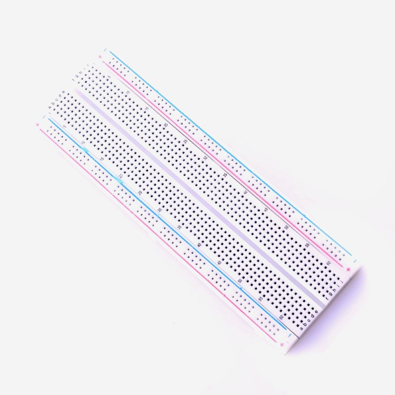
Before you begin using a breadboard, it's essential to gather all the necessary materials and components. Here's what you'll need:Breadboard: A typical breadboard consists of rows and columns of interconnected metal clips. It usually has two sets of long rows on either side and shorter rows in the middle.
Electronic components: These can include resistors, LEDs, capacitors, transistors, integrated circuits (ICs), wires, and any other components you plan to use in your circuit.
Power source: Depending on your circuit, you may need a battery, a power supply, or another source of electricity.
Jumper wires: These wires come with pre-attached pins that fit into the holes on the breadboard, allowing you to connect components and create electrical pathways.
Step 2: Understand the Breadboard Layout
Before diving into your circuit, it's crucial to understand the layout of the breadboard. A standard breadboard is typically divided into two sections, each with its unique purpose:A. Terminal Strips
Power Rails: The two vertical columns on the sides of the breadboard are known as power rails. One is typically labeled as "+," and the other as "-." These are used for connecting the power supply or battery to your circuit.Bus Strips: The horizontal rows of interconnected clips are called bus strips. They are usually labeled with numbers and letters for easy reference. These rows are used for making connections between components.
B. Component Placement Area
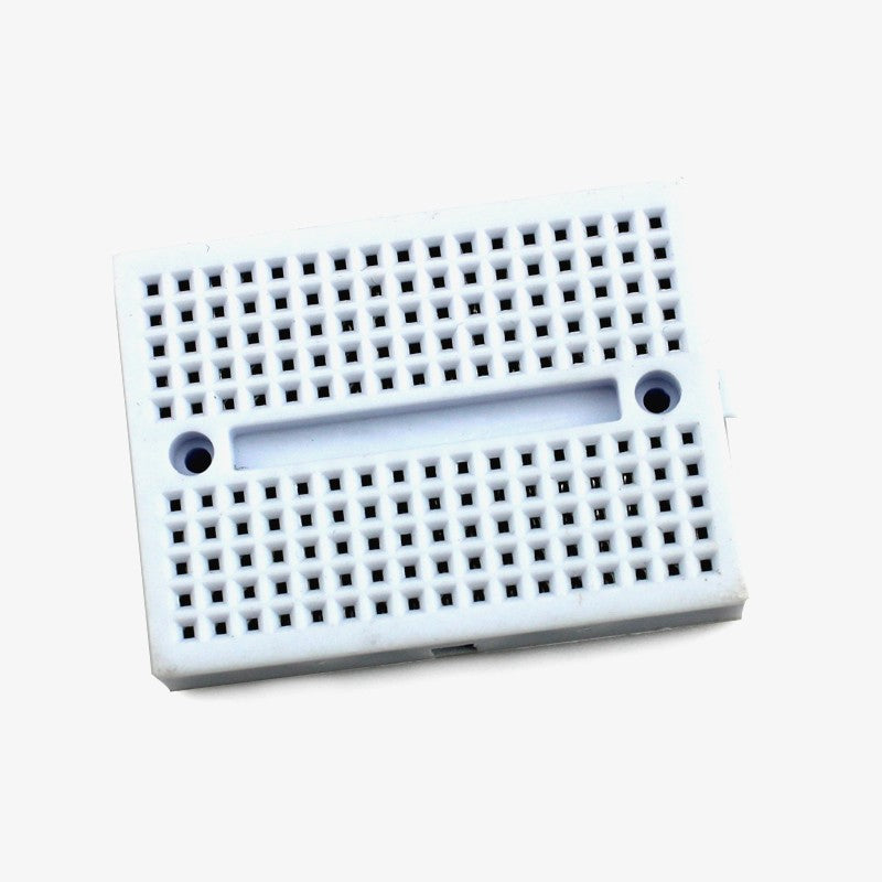
Component Rows: The central area of the breadboard consists of multiple rows of interconnected clips. These are where you will place your electronic components, such as resistors, LEDs, and integrated circuits.Step 3: Plan Your Circuit
Before you start placing components on the breadboard, it's essential to have a clear plan for your circuit. Create a schematic diagram or sketch out how you want to connect your components. Identify which components need to be connected to power and ground, and decide on the placement of each element on the breadboard.
Step 4: Place Components on the Breadboard
Now that you have a plan in place, it's time to start placing your components on the breadboard. Follow these steps:A. Insert Components
Begin by placing the components with two leads (such as resistors or LEDs) into the breadboard. Ensure that each lead goes into a separate row, not connecting them in the same row.For components with more than two leads (such as integrated circuits), carefully align each pin with the appropriate row on the breadboard. Double-check the datasheet for your component to ensure correct pin placement.
b. Connect Power and Ground
Connect the positive (red) and negative (black) wires from your power source (battery or power supply) to the respective power rails on the breadboard. This provides the necessary voltage for your circuit.Step 5: Create Connections with Jumper Wires
With your components in place and power connected, it's time to establish connections between them using jumper wires.A. Select the Appropriate Wire
Choose a jumper wire of the required length and strip the ends if necessary. Jumper wires come in different colors, which can help you organize your circuit and differentiate between connections.B. Connect Components
Insert one end of the jumper wire into the hole adjacent to the component lead you want to connect. For example, if you want to connect a resistor to an LED, insert one end of the jumper wire into the row where the resistor lead is and the other end into the row where the LED lead is.Ensure that the wire makes a secure connection by gently pushing it into the hole.
Repeat this process for all the connections in your circuit, following your schematic or plan.
Step 6: Test Your Circuit
Before powering up your circuit, it's a good idea to double-check all connections and components to ensure they are correctly placed and wired. Verify that there are no loose connections or accidental shorts between adjacent rows.A. Inspect the Circuit
Visually inspect your breadboard to ensure that there are no loose wires or components. Make sure that all components are correctly seated in their respective rows.B. Check for Shorts
Look for any unintended connections (shorts) between adjacent rows. Make sure that jumper wires do not accidentally touch each other or cross rows.Step 7: Apply Power
Once you are confident that your circuit is correctly assembled, you can apply power to see if it works as expected.A. Turn On the Power
If you are using a battery, connect it to the power rails. If you are using a power supply, set the voltage to the desired level and connect it to the appropriate power rails.B. Observe the Circuit
Watch for any signs of activity in your circuit, such as LEDs lighting up or motors spinning. Use a multimeter to measure voltage or current at various points to verify that your circuit is functioning as intended.Step 8: Troubleshoot and Iterate
If your circuit does not work as expected, don't worry. Electronics often involve troubleshooting and iteration. Here are some common troubleshooting steps:A. Double-Check Connections
Inspect your breadboard carefully to ensure that all connections are secure and correctly placed. Look for loose wires or components.B. Check Component Values
Verify that you have used the correct components with the appropriate values. Sometimes, using the wrong resistor or capacitor value can affect the circuit's performance.C. Test Components Individually
Isolate components and test them individually to ensure they are functioning correctly. This can help identify faulty components.D. Review Your Schematic
Double-check your schematic or circuit diagram to ensure that you have wired everything correctly according to your plan.E. Seek Help and Research
If you are stuck, don't hesitate to seek help from online forums, tutorials, or experienced electronics enthusiasts. They can provide valuable insights and solutions to common circuit problems.Step 9: Document Your Circuit
Once you have a working circuit, it's essential to document your design for future reference or sharing with others.A. Create a Schematic Diagram
Draw a clear and detailed schematic diagram of your circuit. Include component values, connections, and power supply information.B. Take Photos
Take photographs of your breadboard setup from multiple angles. These photos can be helpful if you need to recreate the circuit later.C. Label Components
Use labels or markers to identify components and wires on the breadboard. This makes it easier to understand and modify your circuit in the future.


Comments
Post a Comment