Design Multiplexer and Demultiplexer ICs using VHDL on Modelsim
In the world of digital electronics, an integrated circuit called the “Multiplexer” is a device often used for the selection process. Let's dig deeper into what Multiplexer is, its specifications, and how we can design one using VHDL in Modelsim. If you are new to VHDL, check out Getting Started with VLSI and VHDL using ModelSim – A Beginners Guide.
What is Multiplexer?
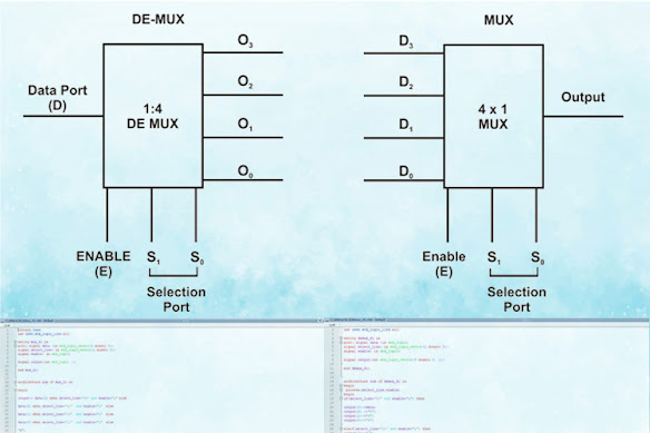
A multiplexer is a device that selects and merges together several analog or digital signals for transmission on a single line. Multiplexer has input and output ports. This combinational circuit select/switch between the available input data and map it to the output port.
How to Design Multiplexer using VHDL?
Library ieee;
use ieee.std_logic_1164.all;
entity mux_41 is
port( signal data :in std_logic_vector(3 downto 0);
signal select_line: in std_logic_vector(1 downto 0);
signal enable: in std_logic;
signal output:out std_logic  );
end mux_41;
architecture sim of mux_41 is
begin
output<= data(3) when select_line="00" and enable='1' else
data(2) when select_line="01"  and enable='1'  else
data(1) when select_line="10"  and enable='1'  else
data(0) when select_line="11"  and enable='1'  else
'X';
end sim;
What is a Demultiplexer?
How to Design Demultiplexer using VHDL?
Library ieee;
use ieee.std_logic_1164.all; entity demux_41 is port( signal data :in std_logic; signal select_line: in std_logic_vector(1 downto 0); signal enable: in std_logic; signal output:out std_logic_vector(3 downto 0 )); end demux_41; architecture sim of demux_41 is begin process(select_line,enable) begin if(select_line="00" and enable='1') then output(3)<=data; output(2) <='0'; output(1)<='0'; output(0)<='0'; elsif(select_line="01" and enable='1') then output(3)<='0'; output(2) <=data; output(1)<='0'; output(0)<='0'; elsif (select_line="10" and enable='1') then output(3)<='0'; output(2) <='0'; output(1)<=data; output(0)<='0'; elsif (select_line="11" and enable='1') then output(3)<='0'; output(2) <='0'; output(1)<='0'; output(0)<=data; else output(3)<='X'; output(2) <='X'; output(1)<='X'; output(0)<='X'; end if; end process; end sim;

Comments
Post a Comment