Posts

Showing posts from June, 2022

Design Multiplexer and Demultiplexer ICs using VHDL on Modelsim

Image
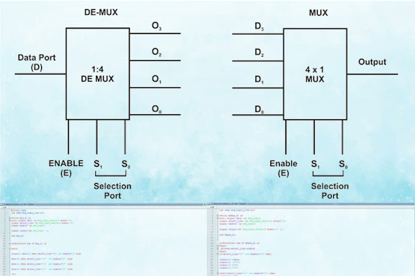
In the world of digital electronics, an integrated circuit called the “Multiplexer” is a device often used for the selection process. Let's dig deeper into what Multiplexer is, its specifications, and how we can design one using VHDL in Modelsim. If you are new to VHDL, check out Getting Started with VLSI and VHDL using ModelSim – A Beginners Guide . What is Multiplexer? A multiplexer is a device that selects and merges together several analog or digital signals for transmission on a single line. Multiplexer has input and output ports. This combinational circuit select/switch between the available input data and map it to the output port. How to Design Multiplexer using VHDL? First, I will provide the entire code written to design the Multiplexer. The VHDL Multiplexer code is below. Library ieee; use ieee.std_logic_1164.all; entity mux_41 is port( signal data :in std_logic_vector(3 downto 0); signal select_line: in std_logic_vector(1 downto 0); signal enable: in std_logic; signal o

What is an Ultrasonic Sensor and how it works?

Image
If you are new to electronics, you might have so many questions like what is an Ultrasonic sensor? How it can measure the distance of any object? In this section, we will try to find the answers to such questions. Once you have all the required components with you, you can follow the steps mentioned below and work on the project. Take a look at the picture of an ultrasonic sensor below. On the left, we have the front view of an ultrasonic sensor and on the right side, we get to see the backside view of the ultrasonic sensor. We have two transducers at the front of this sensor that you can see in the first image. One transducer is used to transmit, the ultrasonic burst at 40kHz, and another one receives the reflected ultrasonic burst. We have 2 pins (i.e. Vcc and GND) for powering up the sensor and 2 pins (i.e. Trigger and Echo) for measuring the distance. Now, let’s try to understand the working with the help of timing diagram below. At first, we need to set the Trigger pin of the ultr

How to Choose Desired Inductors for Your Application?

Image
Different types of inductors pose different specifications in different parameters. Due to the difference in inductor parameters, specific applications require special types of inductors. Therefore, It is essential to know what are the  different types of parameters  processed by an inductor. Any Inductor will have the following parameters- Inductance. Coil DC resistance or DCR. Rated current. Core construction and permeability. Self-Resonant frequency. Generally, in CCM (Continuous conduction mode), a higher value inductor is required than the DCM (Discontinuous conduction mode). The SRN8040 series offers inductor values from 0.5uH to 100uH. The next step is to determine the inductor current. Inductor offers two types of inductor current, RMS current and saturation current. RMS current is the equivalent DC current that will pass through the inductor. It is important to select larger I rms  inductors than actually required. The saturated current is the limit when the inductor w

Build your own Wireless Stethoscope with Arduino and HC-05 Bluetooth

Image
  Most heart diseases are associated with and reflected by the sound that the heart produces, and one of the easiest and cheapest ways of diagnosing cardiac dysfunction is by Heart auscultation i.e listening to the heart sound. Now if we are talking about traditional auscultation, that requires experience and good listening skills. That is why in this project we thought to build an electronic stethoscope that will be able to get the heart rate of the human body and we can display the data in a Bluetooth-based serial terminal window.  How Does Wireless Digital Stethoscope Work?  In order to get the heartbeat data, we will first get a stethoscope and cut it in half to fit a condenser microphone, so that we could get the heartbeat sound from the stethoscope. Next, we will make an amplifier with an op-amp and amplify the signal from the microphone so that we could read it with the ADC of the Arduino. But before reading the signal, we will pass it through a low pass filter that will reject